Safety
Product description
Included as standard
Specification
Installation
Flushing and venting
Electrical connection and setting the speed
Control module
Delivered condition
Setting the operating mode
Setting the time
Setting running times
Resetting all setting values
Maintenance and replacement
Faults and remedies
Disposal
EU Declaration of Conformity
Contact
Legally binding language
These instructions apply to all specified product series and describe safe and appropriate use at all stages of operation.
Warnings and symbols

General safety information
- Installation, electrical connection and commissioning of the pump may be carried out only by qualified contractors and all general and local safety measures must be observed.
- Operating instructions and associated documents must be complete, legible and accessible at all times.
- Before carrying out work on the pump, read and ensure that you understand the operating instructions.
- This circulation pump is suitable only for water of potable quality.
- The pump should be operated only if it is in technically perfect condition. It must be used only in accordance with intended use, with an awareness of safety and risks, and in accordance with these instructions.
- Before any installation and maintenance work, disconnect the motor from the power supply and secure against reconnection.
- The use, cleaning and maintenance of this device by children aged 8 years or older, persons of restricted physical, sensory or mental capabilities, or persons with limited experience or knowledge is permitted only if they are supervised or instructed in the safe use of the device and understand the associated risks. Children must not be allowed to play with the device.
The BWO 155 BlueOne pumps are DHW circulation pumps driven by a high efficiency, electronically commuted DC motor. They are built on the original VORTEX spherical motor principle and contain a permanent magnet spherical motor.
The speed of the pump is infinitely adjustable.
The pump has LEDs and pushbuttons to display and set the operating state.
Operation
- The pump runs according to the set running times.
- The time and running times are displayed by LEDs (time: red; running times: green; smallest time segment = 30 min).
- In the event of a power failure, the time stops (no power reserve). The selected running times are retained. Once the power supply is restored, the pump runs in the operating state that was last set. The time may have to be set again.
- KT version: The pump is equipped with a thermostat. At a water temperature above 55 °C, the pump switches OFF; it switches back ON when the water has cooled down to below 45 °C. The thermostat function is only active during the selected running times (LEDs with steady green light).
- Pump
- Flat gaskets and selected screw-connection set on pumps with V-pump housing
- Insulating shell for pump housing
- Quick operating guide
Max. delivery head
1,3 mWS
Max. pump rate
950 l/h
Electr. connection
1~115–230 V / 50–60 Hz
Power consumption
2,5–9 W
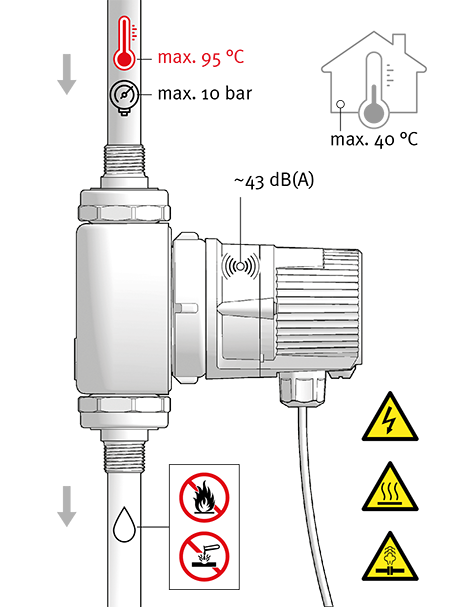
Media temperature
2–95 °C
IP rating
IP44
Permissible water hardness
Unrestricted
Dry-running protection
Yes

CAUTION! Ingress of water will cause physical damage!
- Ensure that the cable entry and cable face downwards after installation.
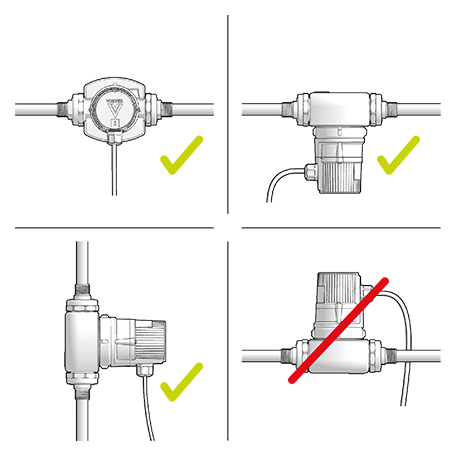
Select a suitable installation site and permissible installation position.
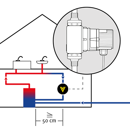
Avoid exposing pumps with thermostatic functions, such as the ERT or SL, to heat:
– Maintain a clearance of at least 50 cm from the DHW heater.
– If the return line opens vertically into the cylinder, install the pump well away from the cylinder entry.
Fit shut-off valves and a non-return valve (Δpmax = 0.2 kPa or 20 mbar).
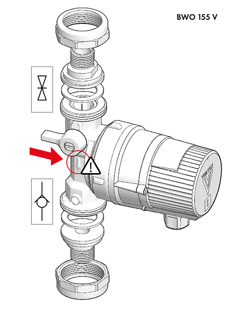
- The integrated shut-off valve in the V-pump housing and the Vortex screw-in valves are only provided to enable a brief shut-off while the motor is replaced.

Integral valves on V pumps
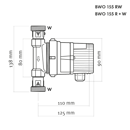
Optional screw-in valves on R pumps (W-valves)
- Integral screw-in valves on BWO 155 RW pump
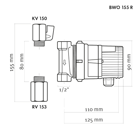
Optional screw-in valves on R pumps (RV 153, KV 150)
When installing the pump, ensure that it is not under strain.
- Observe correct direction of flow.

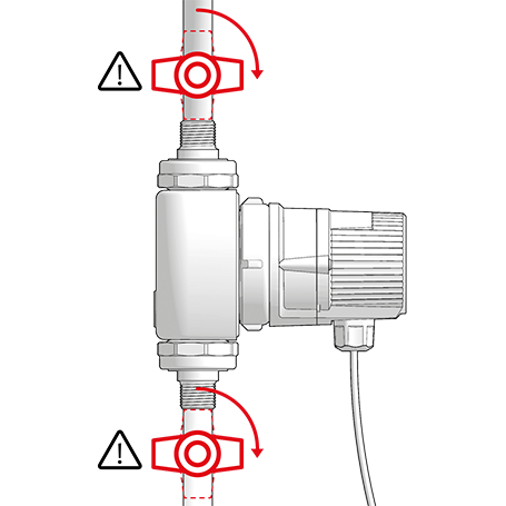
DANGER! Pressurised system!
- Before working on the motor or pump connections, close the shut-off valves.
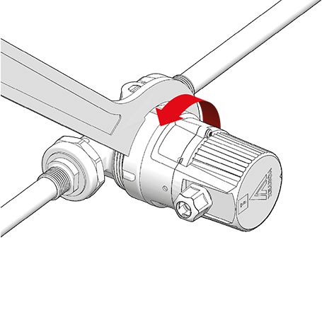
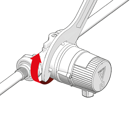
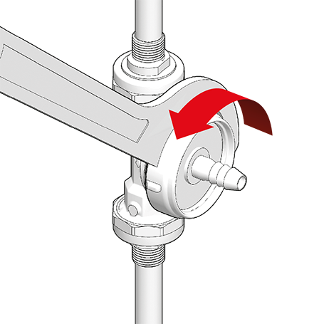
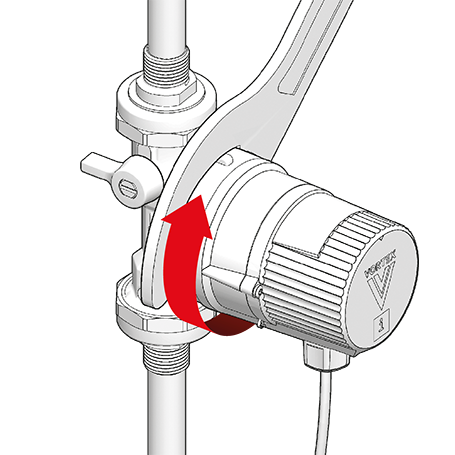
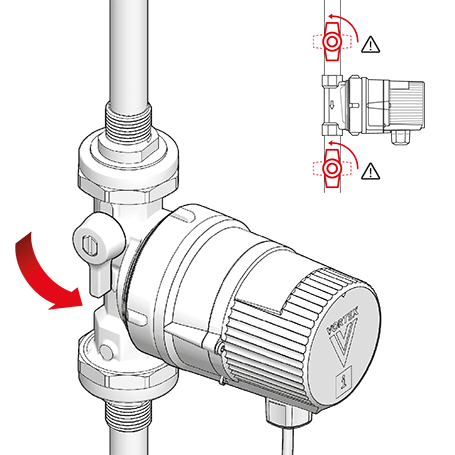
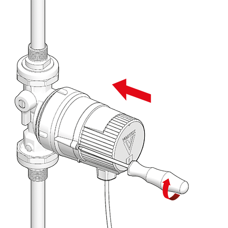
Rotate the pump control panel if necessary so that it is visible (cable exit underneath). To do so, slightly loosen the union nut …
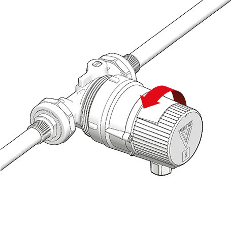
… turn the motor …
… and retighten the union nut (max. 20 Nm).
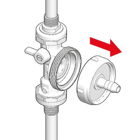
- Fully separating the motor from the pump housing is only necessary for maintenance purposes (see chapters ‘Flushing and venting’ and ‘Maintenance’).
- The pump has dry-running protection. If it runs largely in air, the PCB will repeatedly stop it to protect the rotor bearings. In a fully vented circulation circuit, the pump will run uninterrupted.
CAUTION! Dry-running will damage the bearings!
- Flush the pipework thoroughly with water and vent it.
DANGER! Pressurised system!
- Before working on the motor or pump connections, close the shut-off valves.

WARNING! Risk of scalding due to hot water!
- Avoid direct contact with escaping hot water.
- The pump housing can similarly reach a high temperature due to the hot medium being pumped.
- If no venting valve (fill & drain valve) is present, the system must be vented through the pump housing.
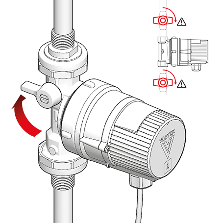
To vent, first close the shut-off valves.
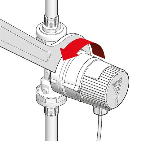
Unscrew the motor from the pump housing …
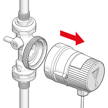
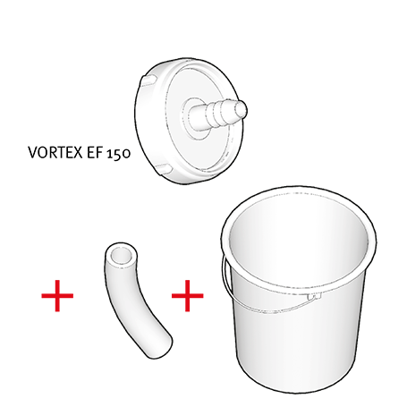
… and screw the venting flange (VORTEX EF 150) onto the motor (max. 20 Nm).
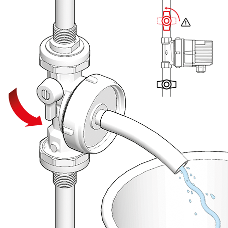
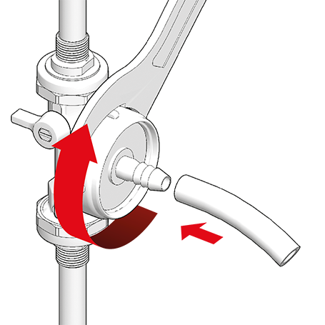
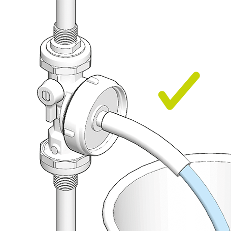
Open the shut-off valve upstream of the pump again and allow water to escape through the venting flange until the pipework is free of air.
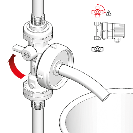
Close the shut-off valve upstream of the pump …
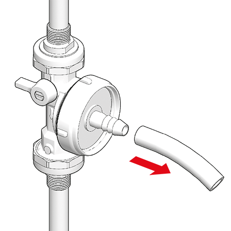
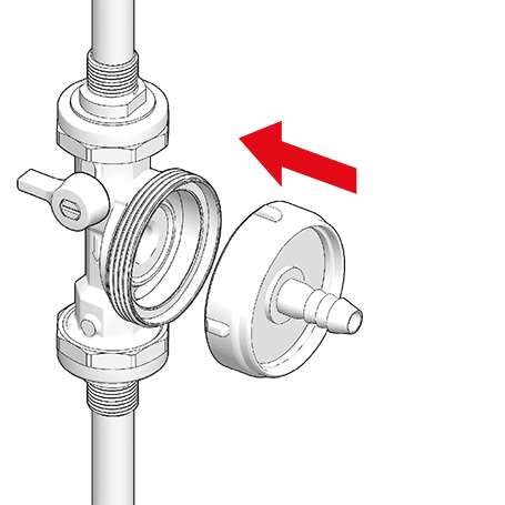
… unscrew the venting flange from the pump …
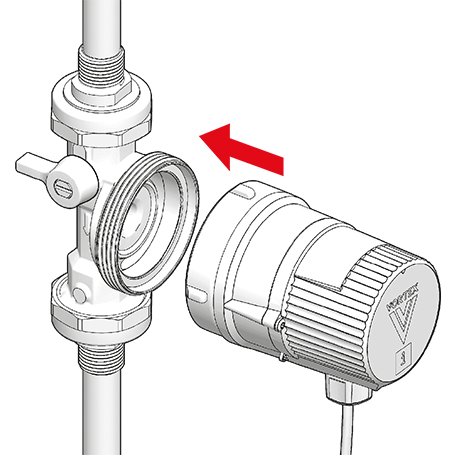
… and reattach the motor to the pump housing.
Retighten the union nut (max. 20 Nm).
Slowly open the shut-off valves again.
- The pump is driven by a DC motor.
- The transformer for AC operation is built into the connection cap.
- As it is in protection class 2, no earth conductor is required.

DANGER! Electric shock can kill!
- Work on the electrics must be carried out only by authorised contractors.
- Disconnect the pump from the power supply and secure against reconnection.
- Check that no voltage is present.
WARNING! Risk of fire due to electrical ignition!
- Ensure that the pump is connected only to the power supply specified on the type plate.
- A permanent connection to the power supply is possible; alternatively use a mains plug with IP 44 rating (provide all-pole disconnection).
- Round cable diameter 5–8 mm
- Wire cross-section 0.75–1.5 mm2
- Strip 8.5–10 mm of insulator from the ends of the wires.
- Twist the wire ends; do not use wire-end sleeves or tinned ends.
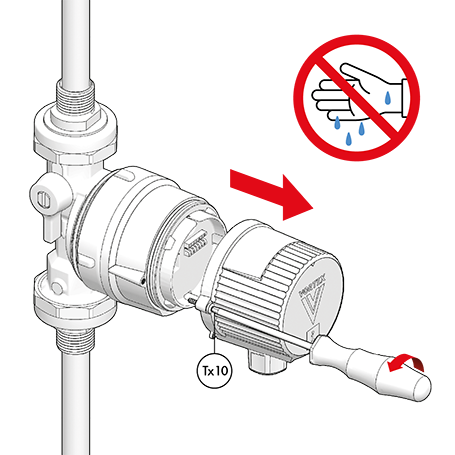
Undo the module cap with a TX10 screwdriver.
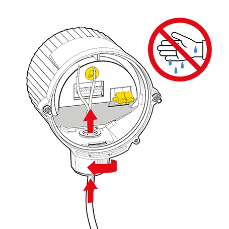
Undo the cap nut and insert the cable.
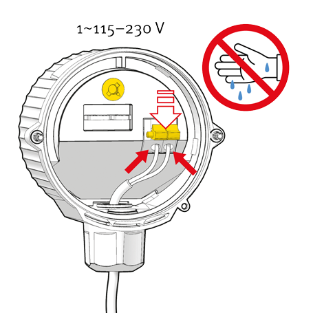
Push yellow lever forward and insert the wire into the red cable terminal. Release the lever again.
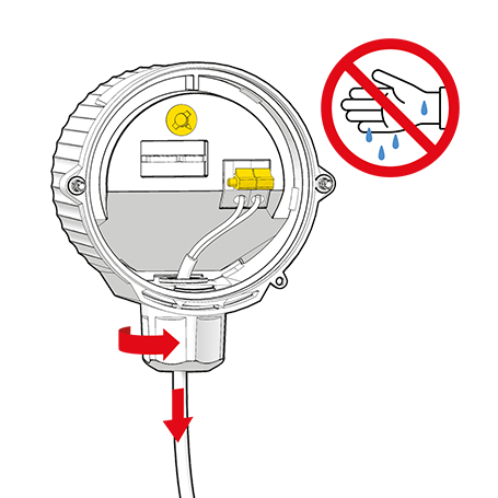
Allow a suitable length of cable and retighten the cap nut.
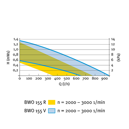
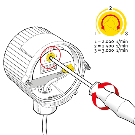
Adjust speed by turning the rotating yellow knob:
1 = min. speed (2000 rpm)
2 = medium speed (2500 rpm = factory setting)
3 = max. speed (3000 rpm), or use any intermediate position.
Screw the module cap on firmly.
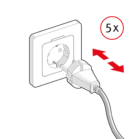
To vent any remaining air, switch the pump on and off several times …
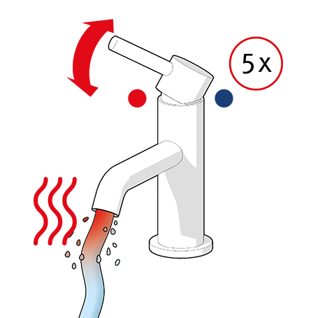
… and open the DHW tap several times …
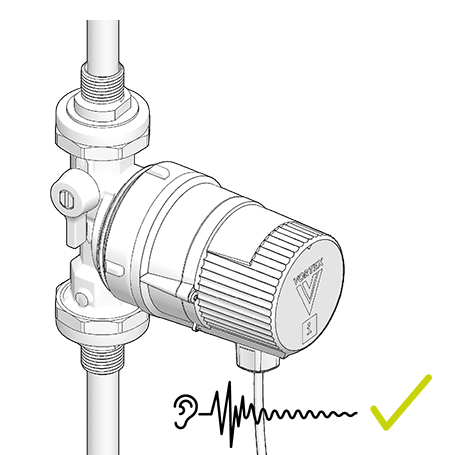
… until the pump runs quietly.


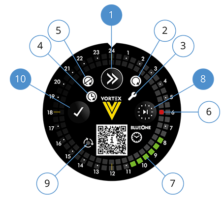
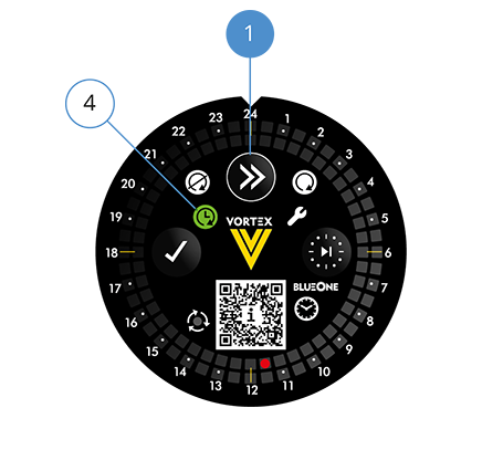
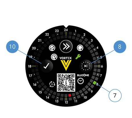
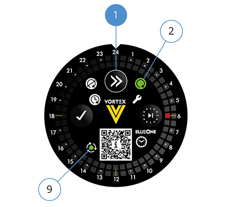
(1) ‘Continue’ button
(2) LED: Pump continuously on
(3) LED: Setting mode
(4) LED: Timer mode
(5) LED: Pump permanently off
(6) LED: Time
(7) LED: running times
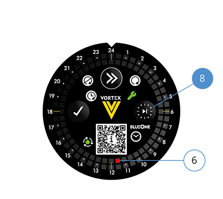
(8) Setting button: Time
(9) LED: Pump monitor (LED green = pump ON) (LED not lit = pump OFF)
(10) OK button
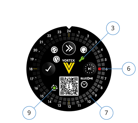
- The pump runs continuously.
- Setting mode LED (3) has a steady green light.
- Pump monitor LED (9) has a steady green light.
- The red time LED (6) in the inner LED ring flashes at 6:00 h (= time segment 6:00–6:30 h).
- None of the green running time LEDs (7) in the outer LED ring light up (48 time segments of 30 min).
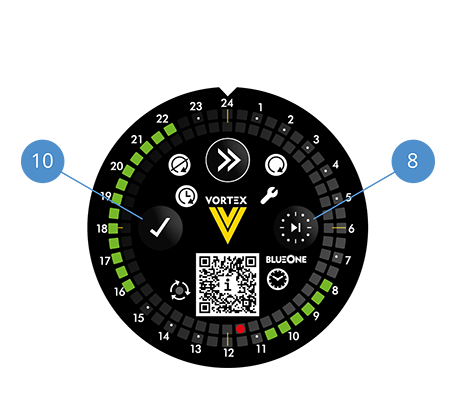
- Press Continue (1) repeatedly until the relevant LED has a steady green light:
– Pump continuously on (2)
– Setting mode (3)
– Timer mode (4)
– Permanently off (pump OFF) (5)
- Pump monitor LED (9): Pump running (LED has steady green light) or not running (LED off).
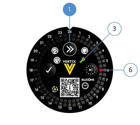
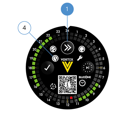
Press Continue (1) repeatedly until the setting mode LED (3) has a steady green light. The time indicator (6) has a flashing red light.
Press the setting button (8) repeatedly until the time LED reaches the current time (11:30 h in this example). Note: The LED moves more quickly if the setting button (8) is held down.
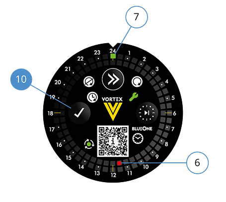
Press OK (10) to confirm. The time LED (6) now has a steady red light. The time has been set. The running time LED (7) 0:00–0:30 h has a flashing green light and already selected running times are indicated.
Press Continue (1) to exit setting mode. Timer mode LED (4) lights up. The time and already selected running times are indicated.
- Press Continue (1) repeatedly until the setting mode LED (3) has a steady green light. The time LED (6) has a flashing red light.
- Confirm the time with OK (10). The time LED (6) has a steady red light. The running time LED (7) 0:00–0:30 h has a flashing green light.
Adding or deleting running times
- Press the setting button (8) repeatedly until the flashing running time LED is on the first required time segment (e.g. 8:00–8:30 h).
- To activate the time segment or delete an already activated time segment, press OK (10). The LED now has a steady green light or is off and the next time segment has a flashing green light.
- Activate this and subsequent time segments in the same way.
- To skip time segments, press the setting button (8) repeatedly. Then press OK (10) to activate or delete other time segments.
- When you have set all times, press Continue (1) to exit setting mode. Timer mode LED (4) lights up. The selected running times are indicated.
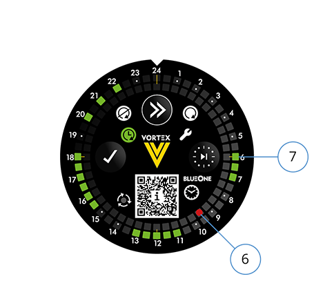
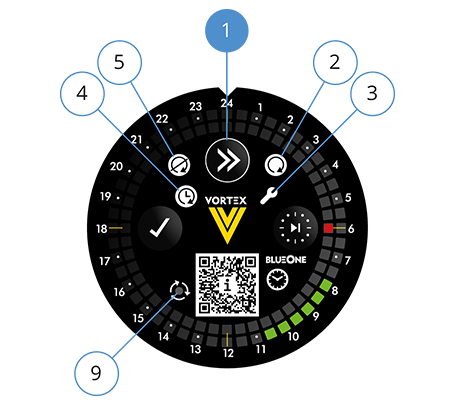
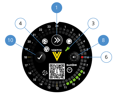
Example of a setting
- The time LED (6) is between 9:30 and 10:00 h.
- Running times (7):
- 06:00–07:30 h
- 11:00–13:30 h
- 15:30–18:30 h
- 20:00–20:30 h
- 21:00–21:30 h
- 22:00–22:30 h
- Press and hold the ‘Continue’ button (1) for 5 seconds.
- All previously set running times are cleared. The time is reset.
- The pump runs continuously. LED indicators (2) and (9) have a steady green light.
DANGER! Electric shock can kill!
- Before working on the pump, disconnect from the power supply and secure against reconnection.
- Check that no voltage is present.
DANGER! Pressurised system!
- Before working on the motor or pump connections, close the shut-off valves.
WARNING! Risk of scalding due to hot water!
- Avoid direct contact with escaping hot water.
- The pump housing can similarly reach a high temperature due to the hot medium being pumped.
- Whenever the motor is opened up, replace the seal in the pump housing.
For maintenance, first close the shut-off valves.
Unscrew the motor from the pump housing …
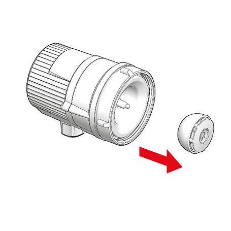
… Carefully lift the rotor off the bearing pin.
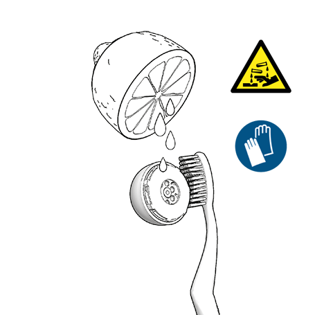
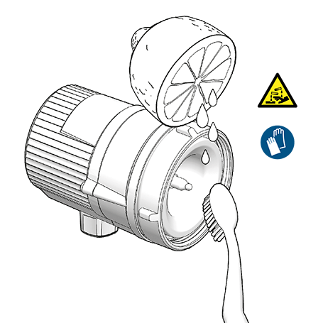
Using a limescale remover, free the rotor and separating cap of limescale. If necessary, replace the rotor. Use only soft, non-metallic tools (e.g. brush, cloth, toothpick).
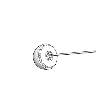
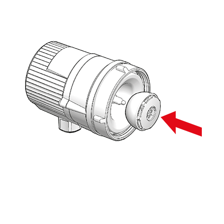
Reposition the rotor on the bearing pin.
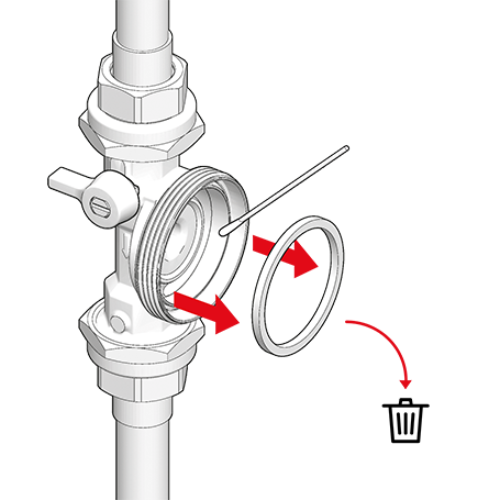
Remove the old seal.
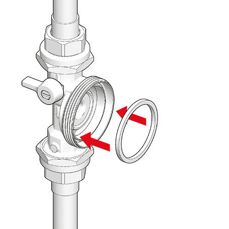
Insert new seal into the pump housing …
… and reattach the motor to the pump housing.
Retighten the union nut (max. 20 Nm).
Slowly open the shut-off valves again.
To vent any remaining air, switch the pump on and off several times …
… and open the DHW tap several times …
… until the pump runs quietly.


This symbol on the product or packaging means that the product must be put into a separate facility for electrical and electronic devices and not disposed of in regular household waste. By disposing of it correctly you will be helping to avoid negative effects to the environment and to human health that may arise from incorrect allocation and handling of old electrical goods.
For further information, please contact your local authority, the waste disposal organisation or the company from which you obtained the product.
This product complies with the applicable European directives and corresponding national regulations and standards.
 272 KB
Deutsche Vortex GmbH & Co. KG
Kästnerstr. 6
71642 Ludwigsburg
Head office
Phone +49 (0) 71 41 / 25 52-0
Fax: +49 (0) 71 41 / 25 52-70
Email:
Legal notice Data protection
The original operating manual is written in German. This version is legally binding. All other language versions are translations of it.